
Electrical Fires
According to the latest statistics from the National Fire Protection Association (NFPA)’s report on “Fires in Industrial or Manufacturing Properties”, electrical distribution and lighting equipment caused 11% of fires and accounted for 15% of direct property damage in industrial or manufacturing facilities from 2009 to 2013.
A key way to prevent electrical fires is through predictive maintenance to detect the onset of a condition that could eventually lead to a fire, then correcting that condition prior to significant deterioration of a component that could cause a fire, catastrophic equipment failures, and unscheduled plant shutdowns.
Predictive Maintenance for Electrical Systems (IR Scans)
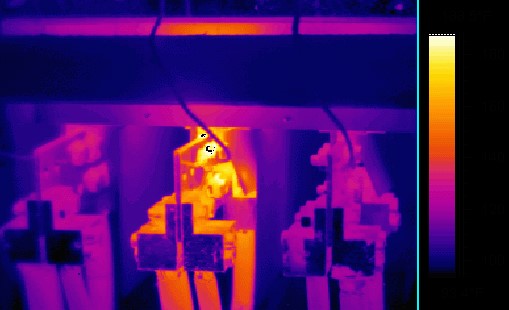
For electrical equipment, a common way to identify conditions that could eventually lead to a fire is to utilize an infrared camera to identify loose or corroded connections, load balance issues, defective breakers and switches, and excessive loads.
Infrared energy is light that is not visible to the human eye. It is the part of the electromagnetic spectrum perceived as heat. Infrared scanning works off the principle that electrical equipment gives off heat, but malfunctioning or overloaded electrical equipment will give off excessive heat due to increased electrical resistance.
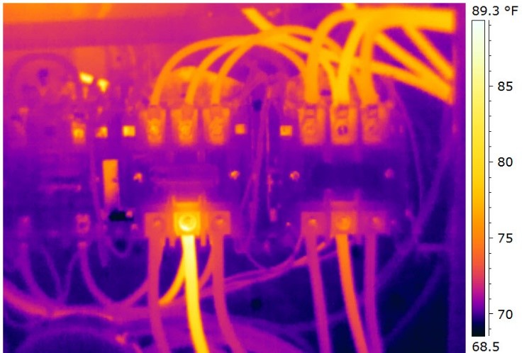
This heat can be detected by an infrared camera, and the various temperatures can differentiate between normal and malfunctioning equipment. The images can then be used to identify exactly what equipment is affected, and how serious the problem is, based on the temperatures and temperature differentials.
Specifically, NFPA 70B – Recommended Practice for Electrical Equipment Maintenance (2016 Ed) Section 11.17.5.6 indicates the following:
- Temperature differences of 1°C to 3°C indicate possible deficiency and warrant investigation.
- Temperature differences of 4°C to 15°C indicate deficiency; repairs should be made as time permits.
- Temperature differences of 16°C and above indicate major deficiency; repairs should be made immediately.
NFPA 70B – Section 11.17 provides guidance on the use of infrared scans to determine the condition of various elements of an electrical power distribution system and to provide information that is used:
- To determine whether any corrective maintenance or replacement is necessary or desirable.
- To confirm the ability of the element to continue to perform its design function adequately.
- To chart the gradual deterioration of the equipment over its service life.
Preparation for Infrared Scan
Very little preparation is required of the organization requesting the infrared scan, however; the thermographer and the qualified electricians opening the panels should follow NFPA 70E – Standard for Electrical Safety in the Workplace. This could include the need for arc flash analysis, training, and specific personal protective equipment (PPE) for all personnel who will be standing in front of open, live electrical panels. [See NFPA 70E – Section 130.7 for details on PPE required]
Infrared Scan
Infrared (IR) scans should be performed while electrical equipment is under load, preferably peak load conditions, but not less than 40% of the rated load of the electrical equipment being inspected.
Infrared scans typically include the main switchgear equipment, motor control centers, electrical distribution equipment (power & lighting), electric motors, transformers, circuit breakers, cable trays, fuses, bus ducts, CRAC units, batteries / charging circuits, and high value electronics.
An IR scan can identify temperature differences that may indicate a problem, but more analysis may be required to accurately diagnose the cause, since a bad connection, an overload, and an unbalanced load may look the same on an IR scan.
Heavily loaded phases will appear warmer, but hot conductors may be either undersized or overloaded, and a cooler-than-normal circuit or leg could indicate a failed component.
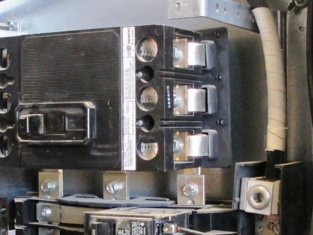

For wiring and connections, a hot spot could indicate a loose, over-tightened, or corroded connection with increased resistance. Defective insulation and broken or undersized wires may also be found.
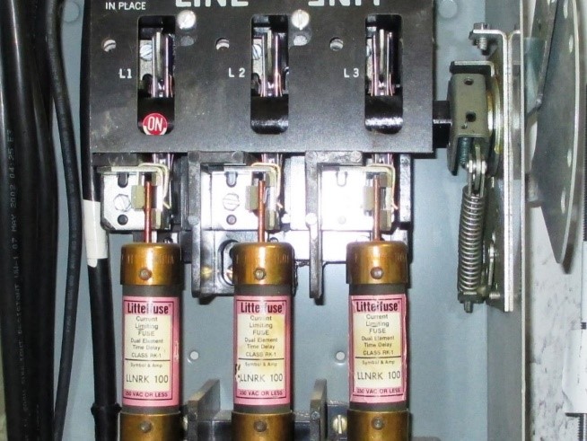
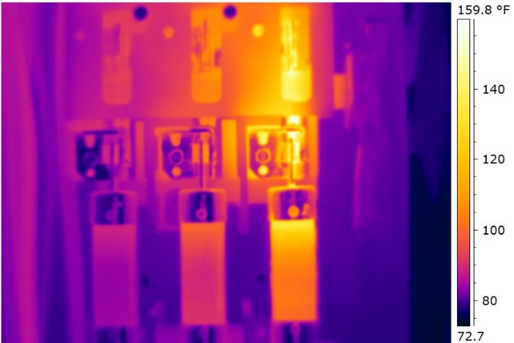
A fuse that shows up as hot may be near its current capacity. (See Figures 4 and 5)
For oil-filled transformers, the high-voltage and low-voltage external bushing connections, cooling tubes, and cooling fans and pumps, as well as the surfaces of critical transformers should all be scanned.
The cooling tubes should appear warm, and oil flow may be restricted, if one or more tubes appear (comparatively) cool. A 10-degree C rise above the nameplate operating temperature of the transformer may reduce the transformer’s life by as much as 50%.
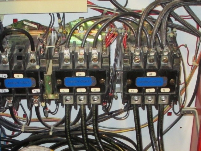
For motor control centers, the contactors, relays, fuses, bus bars, controllers, starters, breakers, disconnects, feeders, and transformers should all be scanned to determine their relative temperatures.
Key items often overlooked in an IR scan include:
- Joints in bus risers and horizontal bus
- Fire pump controllers and associated transfer switches (See Figures 6 and 7)
Note: Efforts should be made to have the fire pump controller scanned during an annual fire pump flow test while the pump is operating at 150% of rated flow. NFPA 25 – Standard for the Inspection, Testing, and Maintenance of Water-Based Fire Protection Systems requires that a loss of normal power be simulated when the pump is operating at peak capacity (150% of nameplate capacity) to cause a transfer to generator power. During this part of the fire pump flow test, an IR scan of the transfer switch should also be conducted.
Documentation (IR Scan)
Following the on-site visit and thermographic (Infrared Scan) of electrical systems, a detailed report is generated that typically includes:
- An overview of the facility and its power distribution systems
- An explanation of IR equipment and techniques utilized in the thermographic scan
- General summary of results and key findings
- Detailed list of equipment scanned, the results of the scan, and prioritized recommendations
- Survey results for each item scanned with item ID, infrared image, correlated photo of equipment, problem description, problem cause, and recommended action/timeframe
Follow-up Actions
Where immediate action is recommended in the report for critical items identified, a follow-up scan should be made once the issue has been corrected to confirm the “hot spot” has been resolved.
Frequency of Infrared Scan
NFPA 70B, IEEE, and NETA all recommend IR scans be conducted annually. Infrared scan of electrical equipment is also a frequent recommendation from property insurance carriers.
Cost of Infrared Scan
The average cost for the infrared scan, analysis, and report is $1000 to $1200 per day. In addition, qualified labor is required to remove/replace the panel covers before and after the IR scan. Two electricians working all day could add another $1000 – $1500, making the total cost fall between $2000-$2500 per day.
Keep in mind, many insurance carriers offer “free” infrared scans for their insureds as a value-added service. This saves the cost of the scan, analysis, and report, but the cost of electricians (if not available in-house) to remove/replace the panel covers during and after the scan would still be incurred by the insured.
Conclusion
Electrical equipment deterioration is normal, and the deterioration process can cause malfunction, electrical failure, and in some cases a fire. Fires that are ignited by electrical distribution and lighting equipment are common in industrial and manufacturing facilities. Predictive maintenance on electrical systems, through infrared scans, is an important part of monitoring the condition of electrical systems in a facility, and can provide early warning of hot spots that could eventually lead to a fire.
Standards
NFPA 70B – Recommended Practice for Electrical Equipment Maintenance (2016 Ed)
NFPA 70E – Standard for Electrical Safety in the Workplace (2015 Ed)